DasDvorak, part 3

In previous posts, we covered taking apart a DasKeyboard, mapping the keys to their corresponding signals on the internal connector, and getting that information neatly cataloged into a MySQL database.  In this part of the series, we’ll be looking at how we’re going to map each key to a unique value, or rather a pair of unique values so we can construct a proper lookup table.

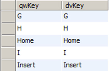
If you recall, we have a table in our database that looks like the following:

dasDvorak01

The key that is a ‘W’ in the qwerty layout represents a comma character in the dvorak layout.  The signal combinations for each are laid out in the qwRow, qwCol, dvRow, and dvCol fields.  When this key is pressed, it will connect pins 7 and 19.  Our programmable logic is going to instead make it look like lines 1 and 21 are connected, thus fooling the host microcontroller into sending a different key code to the host computer.

To do this, we need a series of one bit memories with one memory location for each key.  The problem we now need to solve is to figure out how we’re going to create the mapping between the keys and the memory locations.

After giving the problem some thought, I decided that I would assign a unique number to each key.  To generate those numbers automatically, I created the following table:

dasDvorak04

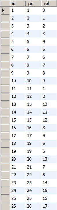
For the moment, ignore the id column (it is a habit of mine to put one in even if redundant).  Basically, this table counts upwards as each row or column signal is encountered.  Since we know that 11, 12, 16, 17. 18, 19, 21, and 22 are the rows, they count in sequence 1, 2, 3, … ending with 8.  The columns do the same, counting from 0 through 17.

This table allows me to use the row and column data to compute a unique memory location for each key.  Even better, once you wrap your head around the next bit of sql, you’ll start to see that the database is going to generate our lookup table for us and it will do it in a way that eliminates manual mistakes that might occur if we tried to do it by hand.  Here is our query:

select 
   (qwC.val * 8) + qwR.val lutAddr,
   (c.val * 8) + r.val tgtLatch
 from keymap k, pinMap c, pinMap r, pinMap qwR, pinMap qwC  
 where k.dvCol = c.pin and k.dvRow = r.pin and k.qwCol = qwC.pin and k.qwRow = qwR.pin
order by lutAddr;

The main idea here is that each of our columns contain 8 rows or keys.  Because of that, we are going to multiply the column value by 8 and then add the row value to it.  This is similar to how you might code a two dimensional array if your language of choice didn’t support two dimensional arrays.  The first element would be 1 and the first element of the second column would be 9, and the first element of the third column would be 17 … and so on.  Here is a snippet of the results:

dasDvorak05

For the first two rows, those keys have no translation going on.  They have the same memory address in both layouts.  When you get to the key assigned to column1, row 3 (pins 1 and 16) that key then gets translated to be something else.  In fact, if you look in the same table, you’ll see that the reverse mapping occurs two rows down.  In this particular example, the ‘=’ and ‘]’ keys have swapped locations.   The original idea was to use this lookup table to determine where to store the state of each key as it was scanned and then to provide a logical expression that would activate the alternate row/column combinations at the right time in the scan sequence.

If one was very well versed in verilog, I’m sure this implementation would be very easy.  Unfortunately, I’m just learning it and am no expert by any means.  Instead, I went through the column/row combinations and figured out a process for storing the information and reading it back to the host microcontroller.  Once I had a process figured out, writing the code was fairly quick, especially since the database had generated the mappings for me using the above query.

As for the current status of the project, I’ve successfully tested the code on edaplayground.com and it pretty much works as I expected.  I then brought the design into the Xilinx ISE, I had a couple of small problems to fix, and then tried to fit the design to a xc2c256 CPLD.  It turns out that the CPLD is a nice fit for the project with the code using just a bit over 60% of the devices resources.

I’m getting close to hardware at this point and will hopefully be providing a schematic soon to help demystify some of what I’ve described so far.  The code needs some tweaks here and there and that should also be coming soon.  The next post will show some rather newbie-ish verilog with some explanation of how we take the table above and turn it into code.

DasDvorak, part 2

Dvorak_keyboard_layout

Above is a graphic from wikipedia.org showing the keyboard layout we’re trying to create.  Note that only the central portion of the keyboard is different.  About half of the keys will remain right where they are.

In this post, we’re going to take a look at how I went about detecting errors in my keymap data.  Any problems we can eliminate early on will be problems we don’t have to deal with later and the database makes this rather easy to do.

We’ll start with identifying our rows and columns again.  We know that pins 11, 12, 16, 17, 18, 19, 21, and 22 are the rows for our key matrix.  Get very familiar with this set of numbers – we will use them a lot as the project progresses.  The first task is to query our table and make sure that both the qwRow and dvRow columns only contain these numbers.  If either column contains anything else, it’s a transcription error that crept into the data somewhere along the way and it needs to be fixed.  Here are a couple of queries that help do that:

select distinct qwRow from keymap;
select distinct dvRow from keymap;

Once those errors are corrected, then the same can be done for the column rows:

select distinct qwCol from keymap;
select distinct dvCol from keymap;

Again, the only thing that should show in the results pane are the columns: 1, 2, 3, 4, 5, 6, 7, 8, 9, 10, 13, 14, 15, 20, 23, 24, 25, and 26.

The final step is a bit more interesting.  Both the qwerty and the dvorak row/column pairs should correlate with each other.  It’s a bit hard to explain how that is, but in the end, we’re checking for consistency between the two views of the table.  These views help in ensuring that the keymap data is consistent.  Here’s the query:

select a.qwKey, b.dvKey
from keymap a, keymap b
where a.qwCol = b.qwCol and
a.qwRow = b.qwRow and
a.dvCol = b.dvCol and
a.dvRow = b.dvRow
order by qwKey;

The trick I’ve used above is an old one that has come in handy many times.  I purposely joined the same table to itself and forced the arrangement of the data so that each keyname from both layouts would be displayed together.  Once this is done, it’s fairly simple to visually scan through the results for problems.    Here is a snippet of the results:

dasDvorak02

If you take a look at a qwerty keyboard and then compare it to the graphic at the top of this post, you can see that where there is a G in a qwerty layout, there would be an I in the dvorak layout.  The Home and Insert keys would remain in their same position in both layouts.

Finally, lets try another query:

select a.qwKey, b.dvKey
from keymap a, keymap b
where a.qwCol = b.dvCol and
a.qwRow = b.dvRow
order by qwKey;

This one will yield a somewhat surprising result.  It will show you two columns of keynames and they should all be the same across each row:

dasDvorak03

This query puts the key translation into the where clause of the query, which makes the result set show if there are any inconsistencies.  At the end of the day, each key can only be represented once for each layout.  The forwards and backwards examination of that translation should be consistent.  If any problems do show up, you have an opportunity to debug it now before we’re about 500 lines deep in verilog code.

Next time, we’ll take a look at how we’re going to implement the key translation.  That post will be mostly about the theory behind the design.  Do note that if you’re not comfortable with sql queries, it might seem to get a little bit more complicated from here, but we’ll really only be using the same multiple-joins trick in a slightly different way.

DasDvorak, part 1

I’ve been typing on a dvorak layout keyboard for well over 5 years now and while OS based mechanisms for changing the keymap do work, the problem I keep running into is that things like the BIOS or UEFI don’t have mechanisms to change the layout from a qwerty based layout.  Furthermore, some applications tend to grab keyboard scan codes directly in the background, bypassing the preferred layout (Dell, please fix your iDrac software so it works correctly).

Normally this wouldn’t be bothersome, but I’m not the average user.  I do systems administration type things which usually take me into those BIOS screens and whatnot on a regular basis.  My home keyboard is an IBM Model M and I got it *because* I could rearrange the keycaps so they would reflect the actual dvorak layout.  At work, I use a DasKeyboard because it gives me the same tactile keyclicks, but there’s no labels on any of the keys.  I find it very frustrating to suddenly be forced into a keyboard layout I don’t use and neither keyboard helps me in that situation.  In those cases, I have to go find a regular keyboard to use temporarily until I’m done with the current task.

So, I wanted to learn verilog and I had a FPGA coming from kickstarter.  I went out and purchased another DasKeyboard and then promptly took it apart.  I think I did plug it in to make sure it worked, but that’s all I did.  Inside the new keyboard there isn’t a lot of space to add other components, so there wouldn’t be any way to make this particular hack invisible, but when I’m done I would have a hardware keyboard that spits out the scan codes in dvorak sequence.  Problem solved.

The way it would work is the host computer would think it has a qwerty keyboard attached, but all of the translation would be done in hardware.  The FPGA would examine the lines that were scanning the keyboard matrix and then either store the state of each key temporarily or it would pass the signal right through back to the keyboard’s own microcontroller.  What happens in the code really depends on what key gets pressed, but we’ll get to a discussion of that a bit later.

For those of you who don’t spend much time looking at USB specifications, the way a keyboard works is it sends sequences of scan codes to the host computer.  The scan code isn’t the same as the key you’re pressing, it’s a number that corresponds to a keymap that’s been published as part of the USB  HID specifications.  The host computer sees the scan code and then uses that same map to figure out what key was pressed.  Some applications, though, have this keymap hard coded to the qwerty keymap and that’s the problem.

So for this part of the write up, the main issue is that once the keyboard is apart, we then need to figure out what pairs of wires become connected when each key is pressed.  In my case, there are 26 lines running from the keyboard microcontroller to the key matrix.  I grabbed a multimeter and then carefully put together a listing of what column and row are connected as each key is pressed.  The engineers that put DasKeyboard together were nice enough to silkscreen the name of each key on the circuit board, so it wasn’t as difficult as I thought it would be.  From this, I learned that pins 11, 12, 16, 17, 18, 19, 21, and 22 are the rows.  The remaining pins are the columns.

At this point in the process, we’ve taken apart the keyboard and gotten a map of where each key fits into the signals used to scan the key matrix.  The next step was then to sit down with a dvorak layout and create something that shows what the signals would look like if it were a dvorak layout.  For this, I started doing it with a spreadsheet, but that wasn’t flexible enough.  I then went to using a MySql database to enter the qwerty key name, the pins used to locate that key, and the dvorak equivalent.  For instance, the letter W in the qwerty layout is identified by signals on pins 7 and 19 of the connector but that key is a comma in the dvorak layout.  To finish this row of data, we’ll also need to know what signals represent a comma in the dvorak layout.  When done, you have something that looks like the following:

dasDvorak01

In essence, when I hit the W key, I want to activate the lines which correspond to the comma instead.  The keyboard’s microcontroller will think I’ve hit a comma and it will send that scan code to the host computer.  The FPGA will see lines 7 and 19 become active, but it will instead activate lines 1 and 21.

This is only part 1 of the project.  There are several other posts coming which describe how I used the database to search for errors in my keymap and how I basically used the computer to generate the logic necessary to do this.  I’m currently writing the verilog code on EDAplayground.com and should be able to code up a testbench soon.  If you have a DasKeyboard and want the keymap data for your own project, let me know.

Asus Nexus 7 … dead?

I have a Google/Asus Nexus 7 tablet and I think it’s the 2013 model (black rubber like back without a chrome bezel).  This is the 32GB model and for the most part, I’ve been very happy with it.  I’ve had very few problems and the size is just about perfect for dropping it into the inside pocket of my jacket.

During the past couple of days, I had turned on the wifi and forgot about it.  As you might imagine, the battery didn’t last long and the device went completely dead.  I found it this morning and plugged it into the original wall charger to charge the battery.  About an hour later, I went to start the device and it just sits there with a white Google logo on a black screen.  I didn’t have time to mess with it as I was trying to get out of the house to go to work.

After I got to work, I gave it a proper charge and yet the tablet still wouldn’t boot past the Google logo.  I contacted Google support and they had me try to boot the device into recovery mode.  That didn’t work either.  When you confirm you want to go into recovery mode, the screen goes black for 1/2 a second and then you get the white Google logo.  It’s supposed to show some kind of secondary screen where you can do a factory reset, but that never shows up and I’ve waited over half an hour for it to do its thing.

Ok, I can live with doing some extra work.  I installed the Android SDK on my machine and downloaded a factory image.  After figuring out a not-so-obvious problem with USB drivers, I can’t seem to get the device to unlock the boot loader.  In fact, any operation in which the system would try to format or clear any of the system partitions usually results in a perpetual wait that never ends.  Again, I’ve waited well over half an hour for it to format or clear the cache partition, which is only 500MB in size.

I’m still researching the issue, but I’m thinking a dead battery shouldn’t cause a product to brick itself.  Maybe the problem was there for a long time and I didn’t notice it because rebooting my tablet is fairly rare.  The unfortunate thing is that I’m not the only person who’s posted about this problem with the 32GB model of this tablet.  At least one other post I read from another user indicated that Asus hardware support had determined that the main board in the tablet was dead and in need of replacement.

I’m wondering if there are more failed tablets out there and users are getting stuck with replacement costs for a device that’s less than 2 years old.  I admit the sample size so far is rather small, but on the other hand, there are a lot of people who don’t opt to complain or post such issues online…

Update: I tried going over this with a hot air rework station to see if it was a cold solder joint and that didn’t fix the issue.  Either it still has a cold solder joint somewhere where I didn’t work on it or it’s truly dead.

I then went to ebay to find a replacement logic board.  I eventually bought a 16GB logic board for about $25.  Once it was installed, the tablet was back up and running.

While I was waiting for parts, I spend a lot of time looking at alternatives.  Far too many 7 inch tablets just don’t fit in an inside coat pocket, but the Nexus 7 does so easily.  I’m not looking forward to the day I have to replace it.

How does MS Windows search for a DLL?

Once upon a time, I was programming in Windows 3.1 using, I think, a Borland product called Turbo C++.  Back then, the operating system didn’t provide true multitasking and each application had to cooperatively give up control so that other programs could run at the same time.  Compared to today’s programming environments, it seemed like the stone age.

One thing that was very important back then was to know how Windows goes about finding custom DLL libraries.  The problem was that there was no version control for DLL’s and it was common for developers of different applications to create DLL’s with the same name.  If the DLL being loaded turned out to be the wrong one, the application would likely crash before the first window even showed up on the desktop.  Knowing the order in which Windows searched for a DLL was important because it was a critical component of fixing the problem.

Today with abstract frameworks handling most everything for you, there isn’t much attention paid to the way DLL’s are loaded and there have been some improvements to the OS which help with the name collision problems of the past.  However, it’s still an important distinction to be aware of when building an application.

For example, at work I have a web server which has about a dozen different custom dotnet websites running on it.  Some of them use the Oracle Data Access Components(ODAC) to be able to read data from backend databases.  We’ve been having a problem with some of these applications crashing at start up because the original application developers deployed the website incorrectly.

Instead of identifying the specific DLLs from the ODAC that were linked with the website, the ODAC was installed on the webserver directly.  The reason why this is a problem is because not every developer uses the exact same version of the ODAC.   If I download the current ODAC, compile my website, and verify it works correctly, it will crash when it’s deployed to the webserver.  The reason for the crash is most likely because my ODAC version is newer than what is installed on the server.  If I then upgrade the version of the ODAC on the webserver, older applications will fail.  I need a solution that lets me deploy new code without having to recompile and redeploy every website on the server.

The solution to this problem is to extract the necessary DLL’s from the ODAC and place them in the bin directory of the deployed website.  The reason this fixes the problem is because Windows will first check the current working directory for any needed DLL’s.  If the correct DLL’s are found, then no further searching is done.  If the DLL’s are not found, then the system will use the %PATH% variable to search for the needed DLL until it is found.  If an older version of the ODAC comes first in the %PATH% variable, then the older applications that were linked with that DLL will work fine and newer applications will crash.  The only easy way to get around the potential version conflict is to put the needed DLL’s into the application’s working directory.

[Note: I’m not going to show the specific details for the ODAC here – there are many online posts that show which DLL’s need to be copied.  Failing that, an analysis of the program’s link structure should reveal what’s required.]

I’m writing this because as time has moved forward, these details seem to be getting lost to time.  Fewer and fewer developers have this knowledge and current programming training tends to skip over OS dependent behavior in favor of ‘run this program on everything and you’ll see dancing unicorns’.  Of course, I’m no expert on the matter, so if you have further information that would be helpful, please let me know.

Migrating to a not-misspelled-domain…

This blog used to be aperature.org and while I used that domain name for some time, it was a fairly bad misspelling and needed to be corrected.  If that wasn’t enough, the name didn’t really reflect the content very well.  When I got the original domain, I was very much into photography.  I migrated into other interests and didn’t change the name.  Besides all that, finding something in a .com, .org, or .net that was original and memorable was very difficult at the time.

So, this is now going to be stderr.info.  I like it because it’s short and it refers to the standard error file descriptor from the standard C library.  While some may think this refers to a medical condition, that’s not the case.  The great thing about TLA’s is that you can always come up with something different than what was intended.  🙂

Complete code for sun_switch project

outsideLight
Some time ago, I started documenting my project to automatically switch on/off some external lighting on the house. You can read the full rationale behind the project in this post. I’ve been delayed in getting this posted because I’ve had other personal projects that have been a higher priority lately.

Today, I’m posting the (nearly) final code for the entire project. All you need to play with this is a WWVB receiver, an Arduino, the TimeLord library, and an optional LED. The LED would be attached to the ssrPin output (with a current limiting resistor) to give an indication of whether the lights would be on or off. Initially, the output defaults to having the lights on. This is so that a power outage in the middle of the night will default to the on state until the system receives a valid time from the WWVB receiver. The LED that’s built into the Arduino is not used for this because I used it in another part of the code to indicate the stability of the received signal. That LED should turn on/off at a rate of once per second if the received signal is clean and free of errors.

There are probably a few bugs in the code at this point, but my testing has shown it to be fairly reliable – enough so that I’m going to be working on a project enclosure as well as some modifications to the electrical in the garage to put this project to good use. I think this code demonstrates a wide range of the capabilities of the arduino. There is some use of the default libraries as well as some custom programming that utilizes the atmega168 hardware directly.

I don’t think I’ll draw the ire of the Arduino haters on this one, but you never know. Personally, I think the flexibility of the platform is something that most of ‘haters’ don’t understand. You don’t have to use any of the libraries if you don’t want to and you can pretty much just skip forward to writing straight C for the mega168 if that’s what you want to do. Personally, I wouldn’t pass up an opportunity to use a development platform with those capabilities; especially when you can avoid spending extra time and money on creating custom boards.

If you want more details and explanations of the code, please read my prior posts.

Source: sun_switch

Translating WWVB time to local time

We’re almost at a point where I can share the final code. One of the minor hurdles I had to tackle was converting UTC time with a day of year value into a more standard Gregorian local time. It turns out that the TimeLord library doesn’t have the facilities for doing this conversion on it’s own – probably because it was designed to work with a real time clock module instead of a WWVB receiver with my clock code.

Below is the code I developed for doing the conversion. This function is much longer than I would have liked, and I try to keep things small so it’s easier to debug. We start off with a definitition of what time zone we’re in. I’m in GMT-5, so the definition goes as follows:

#define timezone -5

Also, we’ll need our definition of ‘struct time t’ which carries the UTC version of our current time:

struct TIME {
  uint8_t seconds;
  uint8_t minutes;
  uint8_t hours; 
  uint16_t doy; // day of year
  uint16_t year;
  uint8_t leapYear;
};

volatile struct TIME t; // our only global variable

If I recall correctly, those are the only definitions that are missing from the following code block. This code tries to generically calculate local time without the added issue of having to jump forward or back due to DST and it should work for all timezones. Note also that a good chunk of the code is trying to compensate for the local day/month/year changing due to crossing midnight on a particular day. I probably didn’t need to worry about that since the actual sunrise/sunset values will only change by about a minute from one day to the other. I guess I was being a little OCD when I wrote this.

// compute gregorian date from time struct t
void getGregorianDate(byte cdate[])
{
  uint8_t months[] = {31, 29, 31, 30, 31, 30, 31, 31, 30, 31, 30, 31};
  uint16_t daysLeft = t.doy;
  uint8_t curMonth = 1;
  int8_t curHour, curDay, 
         curYear = t.year - 2000;
  
  if (t.leapYear == 0)
    months[1] = 28;
    
  while (daysLeft > months[curMonth-1])
  {
    daysLeft -= months[curMonth-1];
    curMonth++; 
  }
  
  // convert our stored UTC time to local time
  if (((int8_t) t.hours + timeZone) < 0)
  {
    // adjust for negative timeZone constant with rollovers 
    curHour = t.hours + 24 + timeZone;
    curDay = daysLeft - 1;
    
    if (curDay < 1) // roll back the month
    {
      // we're actually on the last day of the previous month
      curMonth--;
      curDay = months[curMonth - 1];
    }
    
    if (curMonth < 1) // roll back to prior year
    {
      curDay = months[11];
      curMonth = 12;
      curYear--;
    }
  }
  else // positive calculation with possible rollovers
  {    // note that even if Timezone is a negative constant, this code still works
    curHour = t.hours + timeZone;
    curDay = daysLeft;
    if (curHour > 23) // day
    {
      curHour -= 24;
      curDay++;
    }
    if (curDay > months[curMonth - 1]) // month
    {
      curDay = 1;
      curMonth++;
    }
    if (curMonth > 12) // year
    {
      curMonth = 1;
      curYear++;
    }
  }
  cdate[tl_second] = t.seconds;
  cdate[tl_minute] = t.minutes;
  cdate[tl_hour] = curHour;
  cdate[tl_day] = curDay;
  cdate[tl_month] = curMonth;
  cdate[tl_year] = curYear;
}

Could this be better? Absolutely. I just haven’t taken the time to go through and simplify it yet. There are too many variables being used, for one. I could eliminate all of the curDay, curMonth, and curYear references and use the cdate[] array in their place. I’m also not sure we really have to worry so much about whether the end result of adding the timezone results in a positive or negative value. There’s something there that makes me think I could possibly cut the code for calculating the day, month, and year in half, but the technique for doing so isn’t clear to me just yet. The one good thing I can say about it is that it works great in it’s current form, so I’m leaving it well enough alone for the moment.

Calculating Sunrise/Sunset

sunset

So, now that we have most of the components of this project posted (including this post), I can finally give you the details of what we’re trying to accomplish. My house is situated in a smallish town without a lot of street lighting and the nearest light is too far away to effectively illuminate the house. Even worse than that, I have a driveway that slopes back towards the house creating a small, dark area just in front of the garage door. The problem with this arrangement is that it’s very easy for someone to spend a lot of time trying to steal gas from the one car I have that doesn’t fit in the garage. (funny tip: If you’re trying to steal gas, don’t go after a 4 cylinder, 35 MPG car like the guy in my neighborhood did. There is, on average, less than 4 gallons of fuel in the tank!) To help with this problem, I do have a pair of recessed lights on the house over the garage, but I don’t have a way to effectively turn them on and off at the right time of day. Currently, I have to leave the lights on all the time due to an unpredictable personal schedule of work, family, and friends which isn’t very efficient.

What about a light sensor? I did think of that solution, but that has its own set of problems. Being in the northeast, we get a fair bit of snow in the winter time. That snow can reflect a lot of light and cause the sensor to turn the lights off at the wrong time. Taking it a step further, if someone’s willing to resort to minor criminal activity, nothing would stop them from figuring out some way to fool the sensor since it would have to be mounted on the outside of the house where it would be accessible and visible.

My solution is to use a combination of a RTC, the WWVB time signal, and the TimeLord library to accurately compute sunrise and sunset. The resulting circuit would automatically turn the lights on at sunset and turn them off at sunrise. Not only would this be an energy savings over the course of each day, but with advancements in LED technology, I could reduce my energy use to just pennies per month and get the benefit of having a properly lighted driveway. Furthermore, an addition of some wireless communications could allow me to plot the energy usage over the course of the year. That last feature isn’t planned for this version but it wouldn’t be difficult to do.

So, how do you compute sunrise and sunset? Not being afraid of a little math, I started looking online at the equations necessary to accomplish this. I found this page that had all of the calculations and put together some proof of concept code to see how accurate it would be on the arduino. Being spoiled from working on PC’s I was a little surprised to find that the answers didn’t make much sense. In particular, the trig functions in the avr-libc package tended to give me the most inaccurate values. Furthermore, the calculation of the number of days since the last epoch was giving me a number that was too large to be represented on the microcontroller.

My next thought was to add a floating point processor to the circuit, but the problem with that is 1) added chips take up space, making the project bulky …and… 2) added chips drive up the overall cost of the project. Sometimes the best path forward is the simplest, so I did a search online to see if anyone else had already solved the problem. As it turns out, the TimeLord library does exactly what I needed it to do and it’s very easy to use. My only suggestion for the authors of this library would be to improve the documentation. Sometimes it’s hard to tell if values should be passed as local time or UTC. Beyond that, I would also add functions so that the user can pass either local or UTC without having to do the conversion. However, it did solve my problem without needing any extra circuitry.

I will be posting the full code to this project at a later date. For the time being, though, I’m posting the pieces in the same way I developed the final code which is to say that I put together several small and easy to debug code modules and then later integrated all of them into one large project. The benefit of doing it this way is that it’s much easier and faster to debug small modules than it is to try and put the whole project together in one attempt. Here is the proof of concept code for this week:

#include <TimeLord.h>

// current date - BTW - don't do this if you can avoid it.  Globals are evil.
int curYear = 2010;
int curMonth = 11;
int curDay = 12;

// west longitude and north lattitude - approximate - 
//      I'm not giving you my address in an online code example anyway... :-)
double Lw = -78;
double Ln = 43;

void setup() 
{
  // put your setup code here, to run once:
  Serial.begin(9600);
  
  TimeLord tardis;
  tardis.TimeZone(-5 * 60);
  byte day[] = { 0, 0, 12, curDay, curMonth, curYear }; // noon
  tardis.Position(Ln, Lw);
  if (tardis.SunRise(day))
  {
    Serial.print("Sunrise: ");
    Serial.print((int) day[tl_hour]);
    Serial.print(":");
    Serial.println((int) day[tl_minute]);
  }
  
  if (tardis.SunSet(day))
  {
    Serial.print("Sunset: ");
    Serial.print((int) day[tl_hour]);
    Serial.print(":");
    Serial.println((int) day[tl_minute]);
  }
}

void loop() {}

The next post in this series will have the fully integrated and tested code. I still have some modifications to make to the electrical in my garage to enable this to work, so it may be a while before I can post pictures of the final project. My goal is to have this done and installed sometime before the end of April.

Arduino as a RTC

So, I’ve been putting together this project where I’m receiving accurate time via a WWVB receiver (see previous post). To really make use of this, I need some way to keep track of the time during those times of the day when the WWVB signal isn’t available.

Initially, I looked at the chronodot from Adafruit industries, but one of the things I didn’t like about it was the fact that the battery mounts to the back side of the breakout board. I know that this was done to reduce the cost of the breakout board, but it makes the end result kinda bulky. Besides that, changing out that battery could be tricky depending on how you mount it in your project enclosure. Also, the fact that it’s round doesn’t help when have to mount it into my project case, either.

In addition to considering the chronodot, I also have been waiting on a similar product from Sparkfun.com which is based on the ds3234 real time clock module. Their version, at the time I started development, was simply just the bare timekeeping chip and the breakout for it was unavailable. Fast forward a few months and now the breakout is available, but yet again, the battery is mounted to the back of the board 😦

Not being too sure of the best way to proceed, it hit me one day that I might be able to program the arduino to perform the real time clock functions. Yeah, the crystal that’s on the board may drift with temperature by a few parts per million, but if I’m receiving a valid WWVB signal at some point of the day, I might not need extreme accuracy at all. In fact, after considering the requirements of my project, it wouldn’t really matter if the time drifted by up to 5 minutes over the course of the day.

Below is the proof of concept code I wrote:

// What do you do when an accurate, temperature compensated real time 
//    clock chip breakout is unavailable from your favorite vendors?  
//    Well, you first consider the less accurate battery backed 
//    alternatives until you later realize that there's not really a 
//    big difference between using the non-temp-compensated rtc and 
//    just programming the arduino to do it directly. 
//
//   So - that's what this is.  A real time clock implemented based on 
//    16bit Timer1 and the cpu's clock frequency.  Since both the 
//    dedicated rtc and the this rtc are both dependent on temperature 
//    variations and since both are using crystals for their time source, 
//    the amount of error should be acceptible.  Also, if you integrate 
//    wwvb receiver code with this code, your accuracy should be more 
//    than close enough...

#include <avr/io.h>
#include <avr/interrupt.h>

#define ISR_TIMER1_COUNT 15625 // 16.0MHz clock / (prescaler = 1024)

struct TIME {
  int seconds;
  int minutes;
  int hours; 
};

volatile TIME t;  // global time struct

void setupTimer1(void)
{
  // Setup Clear Timer on Compare Match mode.  We should interrupt each 
  //    time TCNT1 is equal to the value in OC1A register.  TCNT1 will 
  //    automaticall be reset to 0 each time a compare match happens.  
  //    Because this is done in hardware, the interrupt frequency should 
  //    be very stable (no interrupt service routine overhead to deal 
  //    with).
  
  // Please refer to the atmega168 data sheet for an explanation of the 
  //    registers and the values chosen here.
  
  // WGM13:0 = 4  for CTC on OCF1A value.  Prescaler set to divide by 1024.
  TCCR1A &= ~(1<<COM1A1) &   // Clearing bits
            ~(1<<COM1A0) &
            ~(1<<COM1B1) &
            ~(1<<COM1B0) &
            ~(1<<WGM11) &
            ~(1<<WGM10);
            
  TCCR1B &= ~(1<<ICNC1) &    // Clearing bits
            ~(1<<ICES1) &
            ~(1<<WGM13) &
            ~(1<<CS11); 
            
  TCCR1B |= (1<<WGM12) |    // Setting bits
            (1<<CS12) |
            (1<<CS10);
  
  OCR1A = ISR_TIMER1_COUNT;
  
  
  // OCIE1A interrupt flag set
  TIMSK1 |= (1<<OCIE1A);
  
  // Start counter at 0, not that it would matter much in this case...
  TCNT1 = 0;
}

// This interrupt service routine gets called once per second
ISR(TIMER1_COMPA_vect)
{
  t.seconds++;
  if (t.seconds > 59)
  {
    t.minutes++;
    t.seconds = 0;
  }
  if (t.minutes > 59)
  {
    t.hours++;
    t.minutes = 0;
  }
}

void setup()
{
  Serial.begin(9600);
  
  t.seconds = 0;  // initialize our time struct
  t.minutes = 0;
  t.hours = 0;
  
  setupTimer1();
  sei();    // allow interrupts globally
}

void loop()
{
  int sec = t.seconds;
  while (sec == t.seconds) {delay(100);} // wait for t.seconds to increment
  
  Serial.print("Time: ");
  Serial.print(t.hours);
  Serial.print(":");
  Serial.print(t.minutes);
  Serial.print(":");
  Serial.println(t.seconds);
}

You’ll note here that very little of the actual arduino library is used at all. I decided to use the 16bit Timer1 on the microcontroller directly with an interrupt to keep track of the time. When I started monitoring the program, I wrote down the current time on the computer. After 24 hours, I came back and again compared the time on the computer with the time that was coming out of my program and discovered that the time drift was only 3 seconds over the course of a full day! If it performs that well, I guess I don’t need a separate clock chip.

In the next post, I’ll be writing about the TimeLord library.